

Microscale
SN74LS00N IC
SN74LS00N IC
Couldn't load pickup availability
What it is
The SN74LS00N has four independent 2-input NAND gates in a 14-pin DIP. NAND is the "universal" gate: NOT, AND, OR, XOR and simple memory latches can all be built from NAND gates alone. That is why the 74LS00 is the first chip in almost every digital-electronics course and lab kit.
Truth table (each gate)
| A | B | Y |
|---|---|---|
| L | L | H |
| L | H | H |
| H | L | H |
| H | H | L |
The output goes LOW only when both inputs are HIGH.
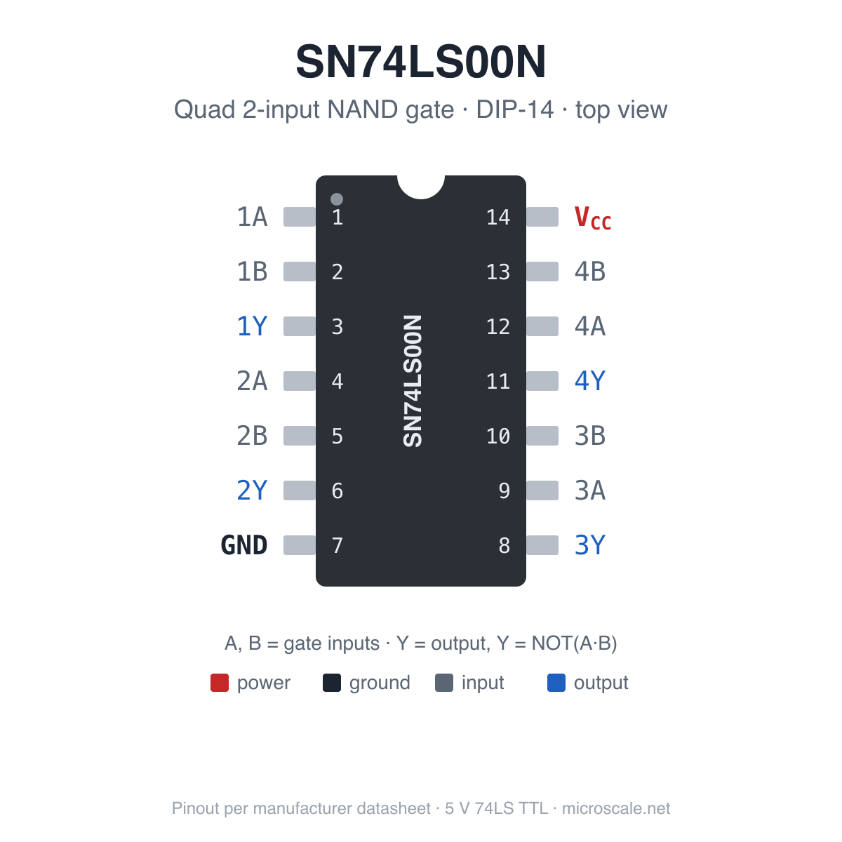
Pinout (DIP-14, top view, notch at the top)
| Pin | Signal | Function | Pin | Signal | Function |
|---|---|---|---|---|---|
| 1 | 1A | Gate 1 input | 14 | VCC | +5 V supply |
| 2 | 1B | Gate 1 input | 13 | 4B | Gate 4 input |
| 3 | 1Y | Gate 1 output | 12 | 4A | Gate 4 input |
| 4 | 2A | Gate 2 input | 11 | 4Y | Gate 4 output |
| 5 | 2B | Gate 2 input | 10 | 3B | Gate 3 input |
| 6 | 2Y | Gate 2 output | 9 | 3A | Gate 3 input |
| 7 | GND | Ground | 8 | 3Y | Gate 3 output |
GND is pin 7 and VCC is pin 14. This is the standard power arrangement for 14-pin 74-series gates.
Specifications
| Parameter | Value |
|---|---|
| Logic family | 74LS (low-power Schottky TTL) |
| Function | Four independent 2-input NAND gates, Y = NOT(A · B) |
| Package | DIP-14 (PDIP, through-hole) |
| Supply voltage (VCC) | 4.75 V min / 5 V nom / 5.25 V max |
| Absolute max supply / input voltage | 7 V |
| Input HIGH threshold (VIH) | 2.0 V min |
| Input LOW threshold (VIL) | 0.8 V max |
| Output HIGH voltage (VOH) | 2.5 V min / 3.4 V typ at −0.4 mA |
| Output LOW voltage (VOL) | 0.35 V typ / 0.5 V max at 8 mA |
| Output current | −0.4 mA source (HIGH) / 8 mA sink (LOW) |
| Input current | −0.4 mA max LOW / 20 µA max HIGH (1 LS load) |
| Supply current (whole chip) | 1.6 mA max, outputs HIGH / 4.4 mA max, outputs LOW |
| Propagation delay | tPLH 9 ns typ, 15 ns max · tPHL 10 ns typ, 15 ns max (2 kΩ, 15 pF) |
| Fan-out | One output drives up to 20 standard 74LS inputs |
| Operating temperature | 0 °C to 70 °C |
Handy circuits
- Inverter (NOT): tie both inputs of one gate together.
- AND: a NAND gate followed by a second gate wired as an inverter.
- OR: invert each input with its own gate, then feed both into a third NAND.
- SR latch / switch debouncer: cross-couple two gates (each output into one input of the other). Pulling one free input LOW sets the latch and the other resets it. This is the classic clean-up for a bouncy push-button.
- Half adder: pair it with the SN74LS86N XOR gate. The sum is A XOR B and the carry is A AND B (two NAND gates).
Wiring it up
- 5 V only. 74LS is TTL logic and needs 4.75–5.25 V on VCC. It will not run reliably from 3.3 V.
- Decouple it. Put a 100 nF ceramic capacitor between VCC and GND, as close to the chip as you can.
- Don't leave inputs floating. An open TTL input usually reads HIGH, but it picks up noise and gives random glitches. Tie unused inputs to VCC (directly or through 1 kΩ) or to GND.
- Arduino Uno / Nano / Mega (5 V): connect directly, no level shifting needed.
- ESP32, Raspberry Pi, STM32 and other 3.3 V boards: a 3.3 V output driving a 74LS input is fine (HIGH threshold is 2.0 V). The other direction is not: a 74LS output can sit around 3.4–3.6 V when HIGH, which is above what 3.3 V-only pins accept. Use a divider (1 kΩ in series, 2 kΩ to GND) or a level shifter, or use the 74HC/74HCT version of the chip instead.
- Driving LEDs: 74LS outputs sink current (8 mA) much better than they source it (0.4 mA). Wire the LED and a 680 Ω–1 kΩ resistor from +5 V to the output, so the LED lights when the output is LOW.
- Unused gates: tie their inputs to VCC or GND so they don't oscillate or draw extra current.
In the package
1 × SN74LS00N in a 14-pin plastic DIP (through-hole, 2.54 mm pin pitch, 7.62 mm / 0.3" row spacing). It drops straight into a breadboard across the centre channel. For soldered builds, use a DIP socket so the chip can be swapped.
The markings depend on the batch: you may get Texas Instruments (SN74LS…N), Hitachi/Renesas (HD74LS…P) or another second-source maker. They are all the same standard 74LS part: same pinout, same logic, same 5 V ratings.
Datasheet
Texas Instruments SN74LS00 datasheet (PDF)
Related: SN74LS86N quad XOR gate (same pinout) · SN74LS112N dual J-K flip-flop