Microscale
Joystick module
Joystick module
Couldn't load pickup availability
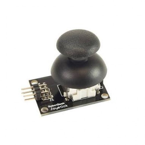
KEY FEATURES OF JOYSTICK MODULE: 2-Axis analog outputs based on the X and Y position of the joystick Pushbutton action when joystick is depressed 3.3 and 5V compatible The joystick module is a fully functional joystick similar to what is found on many game controllers and can be used for a number of different control applications such as for controlling a robotic system.
An acrylic base is also available at the bottom of the page.
Joystick Controls The module includes two spring loaded 5K potentiometers that provide X and Y analog outputs which can be input to two analog inputs on an MCU. There is also a push button switch output if the cap is pressed down until an audible click is heard. The pushbutton output can be connected to any digital input pin of an MCU.
For reference, the X-Axis is motion parallel to the header pins on the module while the Y-Axis is motion perpendicular to the header pins.
The analog inputs on an MCU read values over a range of 0-1023 (for typical 10-bit ADC inputs). The X-Axis and Y-Axis controls should read around 512 (midpoint) when the control is at rest. As the joystick is moved, one or both of the controls will register higher or lower values depending on how the control is being moved. When the joystick is released, it is spring-loaded and will return to center.
The switch output is grounded (LOW) when the switch is pushed. When the switch is at rest, the output is floating, so a pull-up resistor is needed to pull the output high. When using with an MCU, the input pin that the switch is connected to should have the built-in pull-up enabled or else an external pull-up resistor can be used.
Module Connections There is a 5-pin header on the assembly for making connections.
1 x 5 Header
GND = Ground +5V = Vcc (3.3 – 5V) VRx = Analog X-Axis output. Connects to analog input on MCU VRy = Analog Y-Axis output. Connects to analog input on MCU SW = Switch Output, active LOW. Connects to digital input on MCU


